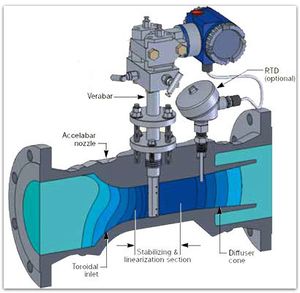
Differential Pressure Flow Meters
Differential Pressure Flow Meters are also known as head type flow meters. They are the most prevalent type of flow meters in use today. It has been projected that more than 50 percent of all liquid flow measurement applications make use of this type of unit. The basic working principle of differential pressure flow meters is based upon the Bernoullis equation which states the fact that the pressure drop across the meter is directly proportional to the square of the flow rate. The flow rate is calculated by measuring the pressure differential and extracting its square root.
Basic Elements
Differential pressure flowmeters consist of two elements.
Primary element
This element causes a change in kinetic energy which results in the differential pressure in the pipe. The unit must be suitably matched to the
- pipe size
- flow conditions
- liquid's properties
Besides, the measurement accuracy of the element must be fine over a practical range.
Secondary element
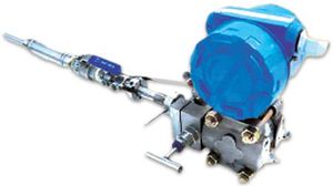
The secondary element measures the differential pressure created by primary element and gives the signal or read-out which is in turn transformed to the actual flow value.
Types of differential pressure flow meters
Most widely used differential pressure flowmeters are:
- Orifice plates
- Flow nozzles
- Venturi tubes
- Variable area flowmeters, i.e. Rotameters
Errors and Noise
In case of compressible fluids, the ratio of differential pressure divided by upstream pressure should not exceed 0.25 for reduction of error and correction of density. Metering errors caused due to wrong installation of the primary element can become considerable i.e. up to 10%. Following are the possible causes of these errors:
- the condition of the mating pipe sections
- insufficient straight pipe runs
- pressure tap and lead line design errors
In turbulent flow conditions, not more than 10% of the d/p signal could possibly be noise produced by disturbances from valves and fittings. These disturbances can be both up- and downstream of the element, and by the element itself. To sort out this noise, a damping is provided in d/p cells which prove to be adequate for majority of the applications. Rigorous noise can be diminished by applying two or more pressure taps connected in parallel on both sides of the d/p cell.

