Fire Alarm Systems
An automatic fire alarm system is designed to detect the unwanted presence of fire by monitoring environmental changes associated with combustion. In general, a fire alarm system is classified as either automatically actuated, manually actuated, or both. Automatic fire alarm systems are intended to notify the building occupants to evacuate in the event of a fire or other emergency, report the event to an off-premises location in order to summon emergency services, and to prepare the structure and associated systems to control the spread of fire and smoke.
Fundamental configuration
Fire alarm control panel
This component, the hub of the system, monitors inputs and system integrity, controls outputs and relays information.
Primary Power supply
Commonly the non-switched 120 or 240 Volt Alternating Current source supplied from a commercial power utility. In non-residential applications, a branch circuit is dedicated to the fire alarm system and its constituents. "Dedicated branch circuits" should not be confused with "Individual branch circuits" which supply energy to a single appliance.
Secondary (backup) Power supplies
This component, commonly consisting of sealed lead-acid storage batteries or other emergency sources including generators, is used to supply energy in the event of a primary power failure.
Initiating Devices
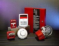
This component acts as an input to the fire alarm control unit and are either manually or automatically actuated. Examples would be devices like pull stations or smoke detectors.
Fire Detection System Components
This policy shall cover all components of fire detection systems including, but not limited to:
- Fire alarm panel;
- Fire alarm annunciator panel;
- Detection devices, such as heat and smoke detectors; and
- Manual pull stations.

