Difference between revisions of "Heat Tracing Systems"
PurplePen19 (talk | contribs) |
|||
| Line 1: | Line 1: | ||
[[Category:Heating]]{{Knoppen}} | [[Category:Heating]]{{Knoppen}} | ||
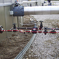
[[File:Heat Tracing System_1.jpg|thumb|200px|right|Heat Tracing System]] | [[File:Heat Tracing System_1.jpg|thumb|200px|right|Heat Tracing System]] | ||
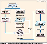
[[File:Heat Tracing System_2.jpg|thumb|200px|right|Heat Tracing System Diagram]] | [[File:Heat Tracing System_2.jpg|thumb|200px|right|Heat Tracing System Diagram]] | ||
'''Heat Tracing System''' is used to compensate for heat losses and to maintain a minimum temperature (i.e. to prevent freezing). In most cases, a heat tracing cable is pulled into trace conduits in long circuit lengths, after the pipes have been field assembled. These trace conduits are factory applied to the pipes prior to insulating and are tested to ensure that no foam has entered into the conduits during the foaming process. | '''Heat Tracing System''' is used to compensate for heat losses and to maintain a minimum temperature (i.e. to prevent freezing). In most cases, a heat tracing cable is pulled into trace conduits in long circuit lengths, after the pipes have been field assembled. These trace conduits are factory applied to the pipes prior to insulating and are tested to ensure that no foam has entered into the conduits during the foaming process. | ||
Latest revision as of 08:43, 2 August 2013
Heat Tracing System is used to compensate for heat losses and to maintain a minimum temperature (i.e. to prevent freezing). In most cases, a heat tracing cable is pulled into trace conduits in long circuit lengths, after the pipes have been field assembled. These trace conduits are factory applied to the pipes prior to insulating and are tested to ensure that no foam has entered into the conduits during the foaming process.
Heat tracing cables are easily installed and controlled. The choice of cable and controls is dependent on the type of pipe being used. Heat tracing cables may be installed continuously on water and sewer lines, or only at specific locations which are susceptible to freezing such as road crossings, fire hydrants, shallow bury locations, etc.
Because of the relatively high cost of electrical energy, these systems are usually installed for freeze protection in the event of a prolonged no flow condition. Systems may also be designed for thawing frozen pipes. Such systems require substantially more capacity to thaw out pipes within a reasonable time limit. Each system must be specifically designed to suit the parameters at hand.
Controls and Processes
Constant watt or “parallel zone” type heat tracing cables are ideally suited for the electric tracing of pre-insulated piping systems. Their fluoropolymer jacket is moisture proof and its slippery texture lends itself to conduit pulling. A wide variety of cables are available for the tracing of pre-insulated pipes. Heat tracing cables and related accessories are rated at 90°C (194°F) and are CSA certified for wet locations to standard C22.2 number 130.
In the case of long pre-insulated pipelines, it may be advantageous to consider a single or three phase 600V system using fluoropolymer jacketed series type heating cables. Each tracing system is custom designed to suit the application.
The electric heat tracing must maintain the pipe temperature above 0°C (32°F) when exposed to the lowest design ambient temperature while at no flow conditions. The installed power capacity must compensate for heat loss through the pipe insulation and include a safety factor.
The temperature controller monitors the pipe temperature and ensures that no energy is wasted by maintaining a temperature very close to the setpoint. This temperature range is a function of the controller's deadband. Typically, heat will be turned "on" at the setpoint and it will be turned "off" at setpoint + deadband. For the UTC line of controls, the factory default deadband is 1°C (1.8°F).
Different controlling parameters are used depending on the piping system involved i.e.: only a control sensor is required on metal pipe whereas an additional high limit sensor is required for plastic pipe protection.
Video

